Monitor for Li-Ion / Li-Poly Battery Packs
with cell balance connector
BM3 for 3S battery pack
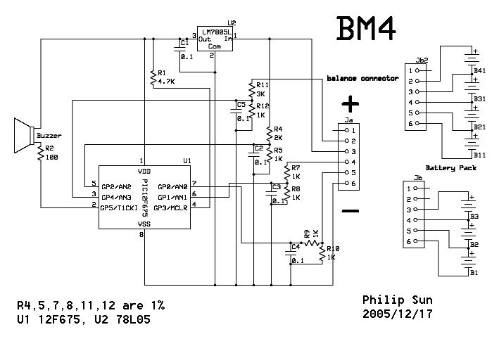
BM4 for 3S / 4S battery pack
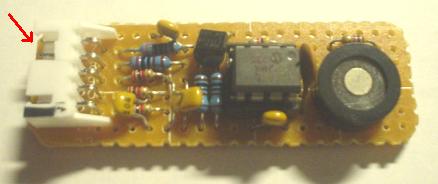
BM4 using 12F675 PIC
A small piece of plastic been cut from the connector (red arrow) to fit both 4 pins and 5 pins balance connector
This device designed to be a "Battery Monitor", which will neither not cut off power nor control your model, but just a alarm.
It has two function, monitor the "unbalance ", and the "over discharge " of each cell, suppose you use 3S1P or 4S1P packs.
1. Unbalance:
When the "voltage difference" between cells > 0.2~0.25 V ( nominal 0.3V ), BM beep a low tone for 1 second and repeat.
2. Over discharge :
When any cell over discharge and it's voltage down below 3.2V, BM beep shortly to indicate which cell is down.
If over discharge been detected, the unbalance detecting function will be disable.
User Manual :
Plug the BM to balance connector of battery pack,
If the battery pack is 14.8V ( 4S ) BM will beep Do~Mi~So~Do to indicate it's OK. if the battery pack is 11.1V ( 3S ) , another two Do~Mi~So~Do sound, to indicate it's OK
To stop the alarm, disconnect the BM from battery pack
You may remark the ASM code to change the default value.
The HEX code in this page (see below) have three different file :
BM3_675_32_03 : define < 3.2 V is over discharge, > 0.3 V (nominal) is unbalance. ( suggested )
BM3_675_34_03 : define < 3.4 V is over discharge, > 0.3 V (nominal) is unbalance.
BM3_675_30_05 : define < 3.0 V is over discharge, > 0.5 V (nominal) is unbalance.
Choose one for yourself!
The sound samples : WAV
BM3 v2.0 using 12F675 PIC
*** BM3 won't update anymore !!!Just plug the device into "balance connector" of battery pack, it well beep Do~Mi~So~Do to indicate it's OK.
If the voltage difference > 0.3 V ( nominal, actually 0.2~0.25V, adjustable within the ASM code), the LED flash and beep 5 sound at lower tone than the sound that indicate battery-low.
When cells run below 3.0V, the LED on and sound beep to indicate which cell is low.
Bi~~~~Bi~~~~ indicate the first cell (B) is low
Bi~Bi~~~~Bi~Bi~~~~ indicate the second cell (B2) is low
Bi~Bi~Bi~~~~Bi~Bi~Bi~~~~ indicate the third cell (B3) is low
So, if you hear Bi~~~~Bi~Bi~Bi~~~~Bi~~~~Bi~Bi~Bi~~~~, it means B & B3 are low
It well continue beep sound until you unplug the battery pack
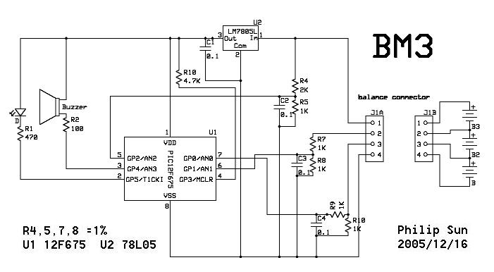
Use 1% resistors for R4,5,7,8 and LM 7805L as regulator, the average deviation error well be better than 0.05V
So....
Voltage AN0 = cell 0
Voltage AN1 = cell (0+1)/2
Voltage AN2 = cell (0+1+2)/3
and transfer to :Voltage cell 0 = AN0
Voltage cell 1 = (AN1*2)-AN0
Voltage cell 2 = (AN2*3)-(AN1*2)
If you want to change the cut-off voltage, just change the ASM code LOW_VOLTAGE EQU D'xxx'
and UNBAL_VOLTAGE EQU D'xx' to change the unbalance detector
;---- VARIABLES DEFINE ----
;
LOW_VOLTAGE EQU D'153' ; (3.0V/5.0V)*255= 153
;LOW_VOLTAGE EQU D'158' ; (3.1V/5.0V)*255= 158
;LOW_VOLTAGE EQU D'163' ; (3.2V/5.0V)*255= 163
;
UNBAL_VOLTAGE EQU D'10' ; (0.2V/5.0V)*255= 10
; ;nominal 0.2V, actually 0.1~0.15V
----------------------------------------------------------------------
I use the ADC at 8 bits resolution, For more precise detection, you may try to rewrite the program to 10 bits resolution.
Keep the wiring short, to prevent interference from speed controller and motor, otherwise add 0.1uF capacitor between PIC pin 5,6,7 and Vss, respectively.
ExpressSCH BM3 schema download
ExpressSCH BM4 schema download
PIC12F675 ASM BM3 V2.0 PIC12F675 HEX BM3 V2.0
PIC12F675 ASM BM4 V1.0 PIC12F675 HEX BM4 V1.0
ATTENTION : It is your own responsibility, if any damage cause by using the web site.
Philip Sun / TAIWAN
PIC programming FAQ
Ruud :
Your pic12f675 asm is not good, as I fed the asm file in to my MPLAB, it the
give error then can I not change the unbal-voltage EQU D'10', please can you
tell my ?
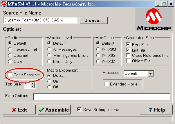
iLuFa : The ASM codes developed under MPASMWIN.exe,
which you can find at "C:\Program Files\Microchip\MPASM Suite", after you
install MPLAB.
Be sure to uncheck "Case Sensitive" in your MPASMWIN.exe setting, or you get
error when compiling, It's due to my ignorance when I wrote the code.
Of course, you can run this ASM code in MPLAB, if you configure your MPLAB
properly, or modify the the ASM file first.
Marian, 13/07:
Hello Bill I found your LiIon/LiPo Monitor realy what I need for my 1/10 car to protect the battery However I need it for 2S(7.4V LiPo pack please can you advise me what I need to modify(most likely in the software for 2S pack usage Thank you very much.
Similar pages: